How to Rewind a Tinywhoop (Or Any Other) BLDC Motor
Tutorial on how to rewind a broken BLDC motor by replacing the windings in the stator.
1. A bit of theory
BLDC motors are DC voltage operating motors. The most important advantage over regular brushed DC motors is the fact of lack of brushes in BLDC motors. BLDC comes from a Brushless DC motor. Thanks to that, fewer parts can wear out and the motor is more reliable and longer lasting. Stator consists of windings made out of copper enameled wire. This means that wire has thin layer of insulation. This insulation may get damaged by excess heat, which occurs during motor stall (not only of course). The motor stall is when we want motors to rotate, but its rotor is locked. Visually burned coils will be black, they will stink quite a lot and some of the isolation may melt, changing the shape of the wire. The damaged motor will ‘try’ to rotate when power is applied, but will only vibrate by moving small steps forward and backward.

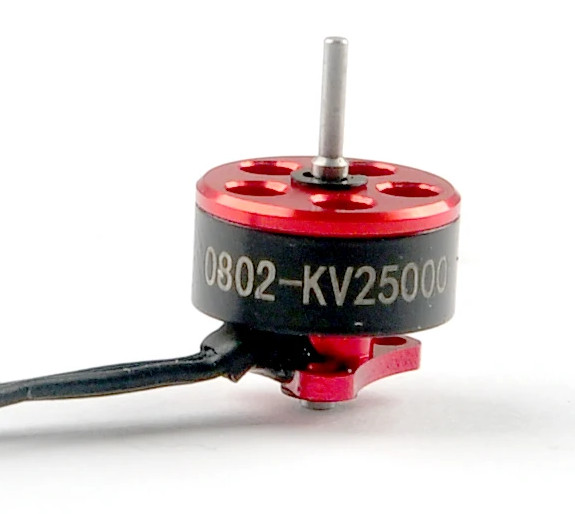
Figure 1. BLDC motor which is to be repaired in this guide. Note that the instructions can be applied to other motors of that kind. Only the windings pattern will change and/or the wire for windings used.
This guide is based on a tiny BLDC motor taken from Mobula 6 tinywhoop. For other motors, the procedure will be the same but the arrangement and parts required may differ.
2. Why repair it by yourself when spare motors can be bought cheaply?
Sometimes we just want to use the motors instead of waiting for the delivery. You may be in luck if the motors you need are available locally and delivery time is in days. But stuff bought from China may have weeks in delivery time. A repair can be conducted now, at the very moment. With the right tools, you will be in the air the same day.
Plus this motor is dead anyway, so why not give it a shot?
Plus plus you will learn something.
3. What will be needed?
There are some
- A bit of patience. Small motors like Mobula 6 are tiny. The winding process may require small fingers and steady hands.
- 0.2mm diameter copper enameled wire can be bought cheaply.
- Good tweezers for catching the E-clip. These clips hold the rotor in place. Can be visible from the bottom of the motor.
- Soldering iron will rather be required.
4. Instructions.
Note: These instructions are written based on the outrunner motor. The outrunner motor is the motor in which the rotor is outside and the stator is inside. Inrunner motors are the opposite. The inrunner motor can be held by hand while spinning, whereas the outrunner only by stator base.
1. Remove the motor from the body of the quadcopter or any frame it is attached to. Disconnect wires. Leave the plug as it may be required later.
2. Remove the E-clip. This is tricky without any special tools. You can use a small screwdriver to push the clip out. The secret is to push it from both sides, but the problem is that it rotates independently from the rotor. One note: E-clip is springy, after successful removal it may fly away and you never going to find it again. The motor can spin without it and for such a small motor it may be an option if you lost it, but for any more powerful motor with a bigger propeller, it is not an option. Put your motor into a plastic transparent bug while removing it. even if it flies away should be easy to find in the bug. To be even more safe, attach a neodymium magnet to the tip of the tweezer to catch the clip.
3. Remove the rotor from the stator. There will be some magnetic force holding it in place, but nothing strong.
4. Cut the plug off, leave some length of wire attached to the winding on the motor since it will be easier to unwind and count the turns.
5. Unwind the damaged windings. Note down the number of turns around each stator arm. If your wires are damaged to the point of being unusable below I did it for you for a described motor. Different motors will require some research, keep in mind source number [1]. which nicely visualizes how the windings should be winded.
For the Mobula 6 SE0802-KV19000 9N12P (12 magnets/poles, 9 stator arms/slots) like these motors counts are as follows:
- the wire is 0.2mm in diameter, enameled copper;
- 10 turns around each stator arm;
- Configuration is Y (star) meaning that in the stator there is a connection of all 3 phase wires;
Make note of which wire is which phase and which end of the wire is start or finish. Preferably use sticky tape and stick it into each note marking for example A start.
For now, leave 10cm at the beginning and at the of each winded phase. It will make life easier afterward. Cut the rest.
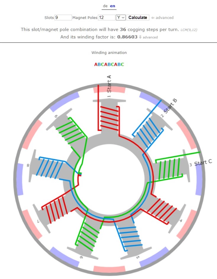
While winding follow the below scheme ABCABCABC**:
(it describes the direction of winding by lower- or uppercase letter and phases order)

Figure 2. Rewinding pattern. Follow the lines from the figure exactly. Start, finish and direction matters! Source: http://www.bavaria-direct.co.za/
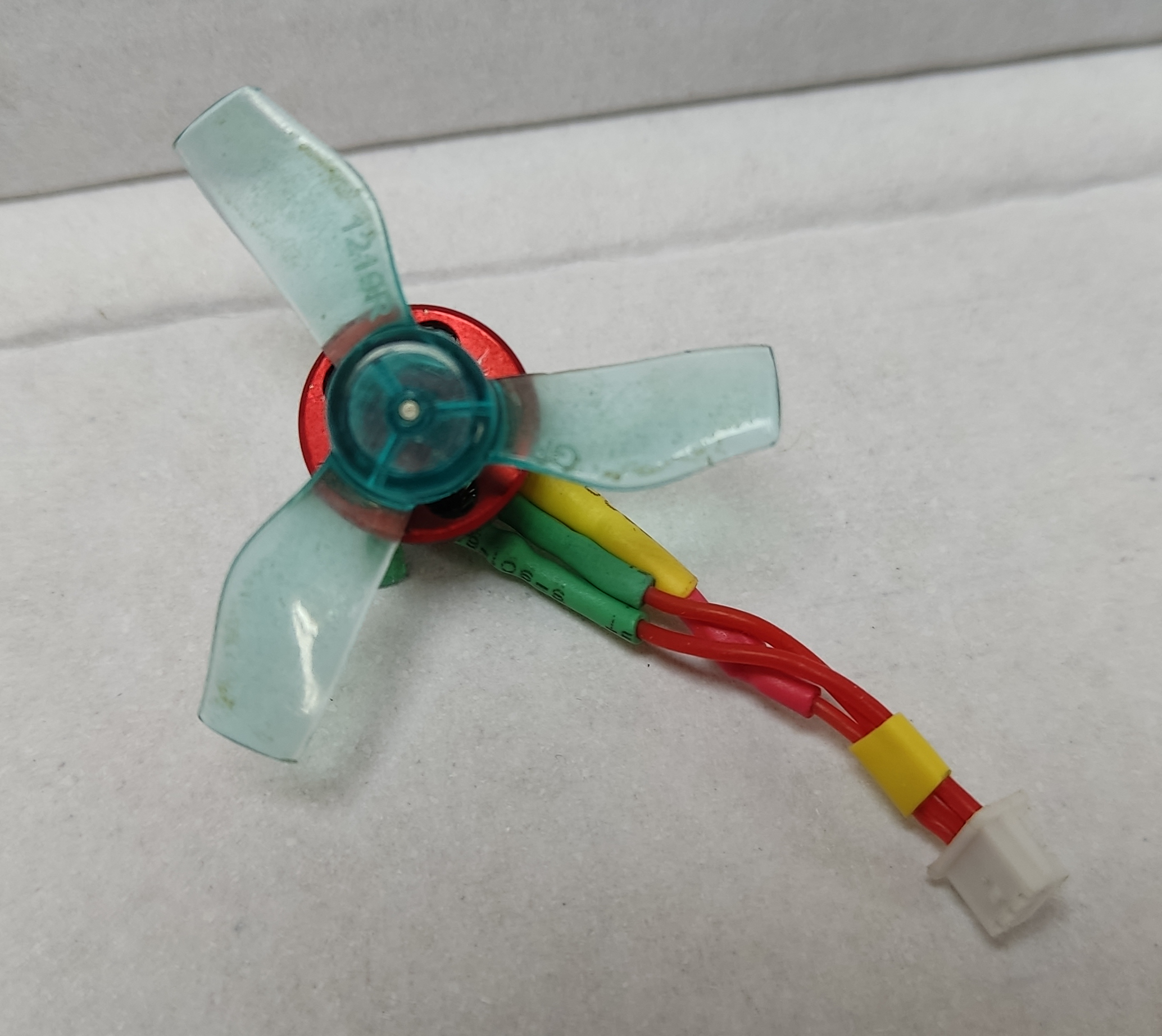
6. When this is done, you are left with 3 phases having each two ends. Make sure that the windings do not interfere with the rest of the motor. Make the Y-center connection as inside the diagram in the Figure above. Place it offside but in the footprint of the motor. Solder the three wires. You may heat the ends with the soldering iron to remove the isolation, but it can damage deeper isolation. Preferably use sandpaper. Do not forget to isolate the solder joint from the rest with heat shrink.

Figure 3. Repaired motor from top. Note the center Y connection.
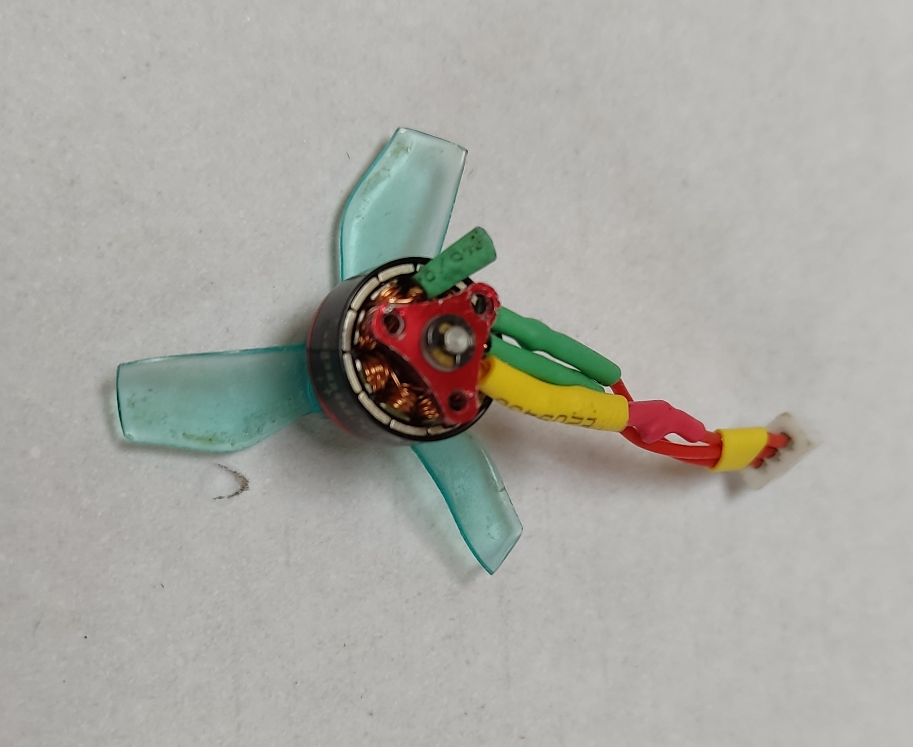
7. Cut the other ends of each phase to the required length. Solder connector if you need one. Now you can text the motor. For the tests, do not assemble the whole motor yet, leave E-clip aside. Just insert the rotor into the stator.

Figure 4. Repaired motor from the bottom. the Y center connection does not interfere with other components.
5. Post stuff
The motor works pretty much the same as the original, but I noted that it starts with a delay concerning the original ones. Higher rotations are required to start it up. You may want to adjust the start-up power in the esc configurator.
6. Sources and useful links
[1] https://www.bavaria-direct.co.za/scheme/calculator/
[2] https://www.rcgroups.com/forums/showthread.php?1076415-Alternative-12N14P-winding
[3] http://www.bavaria-direct.co.za/scheme/common/#prettyPhoto
[4] https://fjp.at/projects/fpv/motor
[5] https://www.machinedesign.com/motors-drives/article/21834666/how-to-calculate-new-dc-motor-parameters-of-a-modified-winding
[6] https://www.instructables.com/Rewinding-a-Brushless-Motor/
