How to Connect GMG12864 Display.

1. GMG12864 display overview
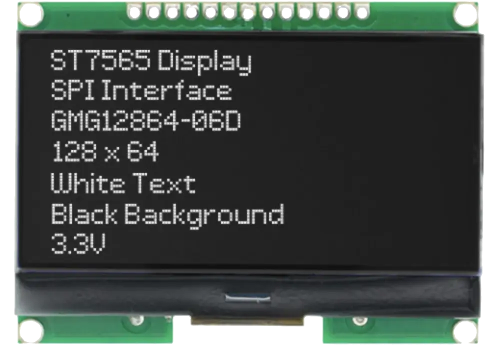
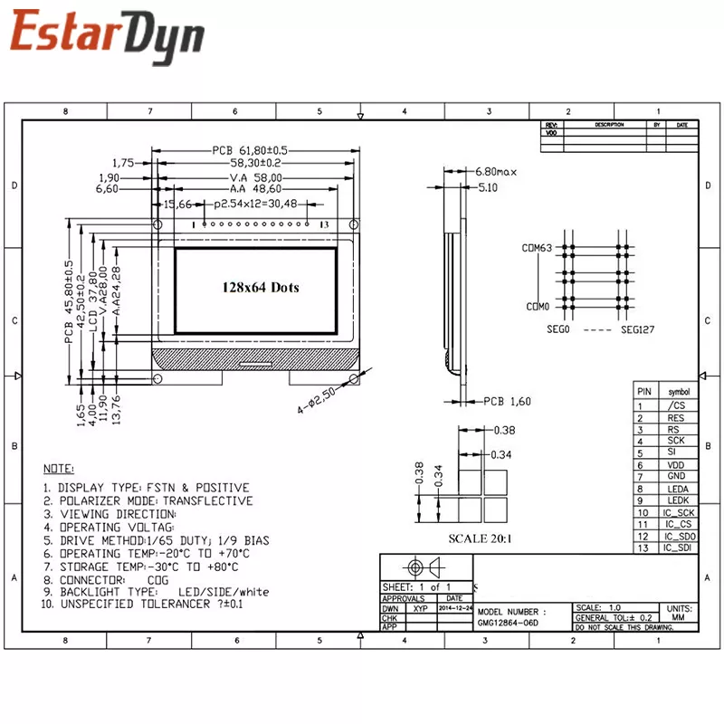
The GMG12864-06D display is and module which can be used with microcontrollers with SPI interface. It runs on 3.3V logic as well as a power. Screen size is: 58 by 28mm, amount of pixels: 128 by 64 pixels. Driver IC is ST7565R.
The display also have the nice texture of the displayed characters which make it more appealing than other screens.

2. Connection with the microcontroller
The problem which may be encountered after the purchase is the connection scheme and how to wire it up so it works. Since the display uses SPI interface it requires a few signal lines. They are not clearly labeled, especially when header pins are soldered. Other problem can be few mystery pins which are not described anywhere. Here I will present the correct labeling so that the display can display!
Since the display uses SPI which requires more data lines than I2C or UART wiring can get messy.
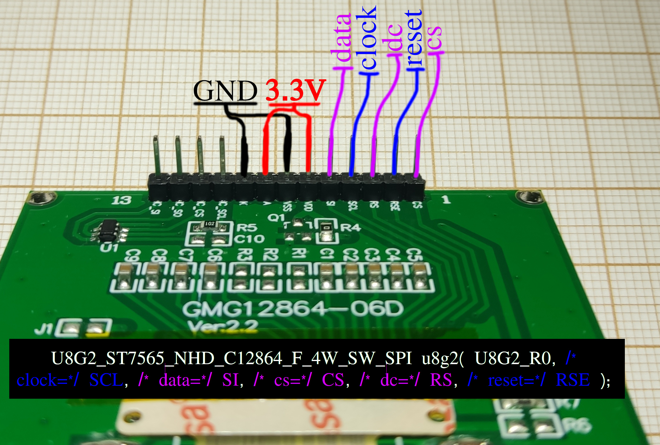
To power display up, it requires 3.3V potential which has to be connected to the A(node) of backlight as well as to driver VDD pin of driver. Same applies to ground connection which goes to VSS and K(athode) as labeled on the PCB.
This tutorial assumes working with u8g2 library which makes very easy to drive different types of displays.
The proper constructor which works for this display is:
1 | U8G2_ST7565_NHD_C12864_F_4W_SW_SPI u8g2(U8G2_R0, |
where:
U8G2_R0 is the rotation of the screen, which can be changed according to the documentation here
clock, data, and cs are SPI pins.
dc is the Data Command pin which differentiate wether sent data to the display is a command (set contrast, rotation, etc) or actual data to be displayed on screen (text, graphics, data, etc)
reset is reset pin which can be used to reset the screen completely or put it into sleep mode.
Starting from pin number #1 (looking from back side of a display and having pin header on top it will be right most pin). Pin number #1 is CS which is stands for Chip Select. This can be connected to any GPIO output pin of microcontroller and has to be pulled low when writing data to display. Connect to cs pin in u8g2 definition.
Pin number #2 is RSE (second from right side). This is to be connected to the GPIO pin assigned to reset of u8g2 library definition. This may come from ‘Register Select Enable’.
Pin number #3 is RS (Register Select most likely). Connect to DC pin.
Pin number #4 is SCL pin. This is SPI Serial Clock (sometimes denoted as SCLK also) pin and has to be connected to a specific pin. On Arduino UNO there is only one pin used for that, on other boards like ESP32 more pins can be defined for that purpose. Connect as to clock definition in u8g2 library.
Pin number #5 is SI. Data Input pin. MOSI in older definition of SPI protocol. This also has to be connected to a specific pin on Arduino UNO. On other boards, can be defined for more pins as user desired. Connect to data pin defined in u8g2.

| Display Pin # (seen from right to left), bottom side | Display Pin | Function | u8g2 library defintion | Micrcontroller pin | Example pin for ESP32-S2 |
|---|---|---|---|---|---|
| 1 | CS | Chip Select, any GPIO with output capabilities | cs | any GPIO | 38 |
| 2 | RSE | Register Select Enable, enable for display | reset | any GPIO | 1 |
| 3 | RS | Register Select, control pin | dc | any GPIO | 3 |
| 4 | SCL | Serial Clock, SPI pin | clock | SCLK | 7 |
| 5 | SI | Serial In, data input, (MOSI) | data | MOSI | 11 |
| 6 | VDD | +Power supply for display driver | - | 3.3V | 3.3V |
| 7 | VSS | -Power supply for display driver | - | GND | GND |
| 8 | A | +Power supply for backlight (normal LED) | - | 3.3V | 3.3V |
| 9 | K | -Power supply for backlight (normal LED) | - | GND | GND |
Now upload example script from U8g2 examples: U8g2 > full_buffer > HelloWorld.ino and display should print out text.
Side Note:
Contrast of the screen may require setting in order to see anything. With very small value the text may not be visible at all and thus, cause confusion. In my testing good starting value is 640 but lower values may be acceptable if screen is to be kept in dark:
1 | u8g2.setContrast(640); |
3. Sources
[1] https://github.com/olikraus/u8g2/wiki/u8g2reference
[2] https://forum.arduino.cc/t/lcd-12864-st7565-13-pin/645789/4
[3] There is also a review on Aliexpress site of some generous buyer (D***v) who figured out the connection and shared it here. Thank you.
[3] Images: https://megashara.biz/ua/p1590813863-arduino-zhk-lcd12864.html,
https://www.aliexpress.com/item/1005001621784395.html,
